From design to trial mold, those links cannot be ignored!
Draw mold diagram
It is required to draw according to the national drafting standards, but it also requires the combination of our factory standards and factory customary drawing methods not specified by the country. Before drawing the final assembly drawing of the mold, a process diagram should be drawn and comply with the requirements of the part drawing and process data. The dimensions guaranteed by the next process should be marked with the words\’ process dimensions\’ on the drawing. If no other mechanical processing is carried out besides repairing burrs after forming, the process diagram will be identical to the part drawing.

It is best to indicate the part number, name, material, material shrinkage rate, drawing scale, etc. below the process diagram. Usually, the process drawing is shown on the mold assembly drawing.
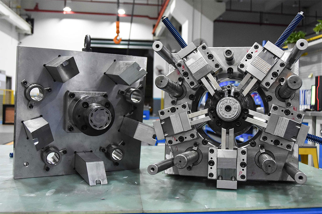
- Draw the final assembly structure diagram
Try to use a 1:1 scale when drawing the final assembly drawing, starting from the cavity and drawing the main view at the same time as other views.
The final assembly drawing of the mold should include the following content:
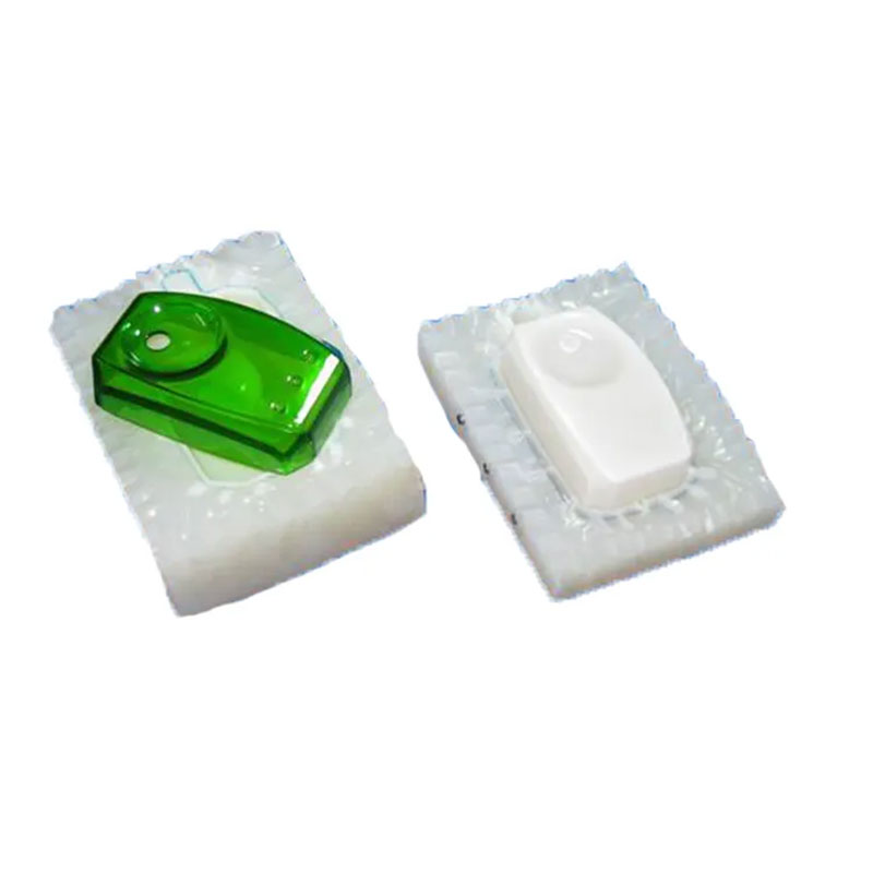
1) The structure of the mold forming part.
2) The structural form of the pouring system and exhaust system.
3) Parting surface and mold taking method.
4) The external structure and the position of all connecting components, positioning, and guiding components.
5) Mark the height dimensions of the cavity (not mandatory, as needed) and the overall dimensions of the mold.
6) Auxiliary tools (mold removal tools, calibration tools, etc.).
7) Number all parts in sequence and fill out the detailed list.
8) Mark technical requirements and instructions for use.
The technical requirements for the mold assembly drawing include:
1) Performance requirements for certain systems of molds. For example, assembly requirements for ejection systems and slider core pulling structures.
2) Requirements for mold assembly process. For example, after the mold is assembled, the fitting gap of the parting surface should not exceed the parallelism requirements of 0.05mm above and below the mold, and the size determined by the assembly and the requirements for that size should be pointed out.
3) Mold usage, assembly and disassembly methods.
4) Requirements for anti oxidation treatment, mold number, engraving, marking, oil seal, storage, etc.
5) Requirements for mold testing and inspection.
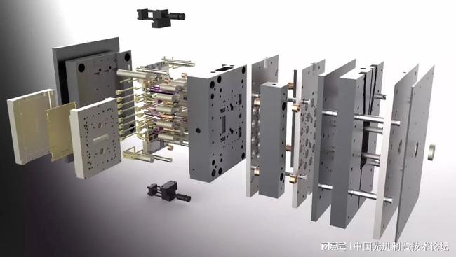
- Draw all part drawings
The order of disassembling and drawing part drawings from the mold assembly drawing should be: from inside to outside, from complex to simple, from forming parts to structural parts.